
User guide
From drawing to program on the machine
A walk through every screen of the app, using a 5-frame CR profile as the example (multiple frames are a PRO feature).
Video tutorial · 38 seconds
Machining a 30° × 3 chamfer on a Ø25 pin
From drawing to G‑code with the CR profile — just 4 fields to fill in.
- Read the drawing: Ø25 pin, 30° chamfer, depth 3 — plus R0.3 to round the cone tip.
- Enter them in CR PROFILE: Dx-A = 25, C1 = 3, α = 30, R = 0.3.
- G‑code + 2D path: N1 T101 roughing, N2 T202 finishing, the running line highlighted.
- Check in 3D: rotate and zoom on the chamfered end — end face Ø21.19.
- Dimensioned drawing: A X25.0 Z-3.0 · B X21.709 Z-0.15 · D X21.189 Z0.
Video tutorial · 53 seconds
Read the drawing, fill in CR‑H: 55° taper · R4 · Ø32 pin
A real drawing never uses the app's field names — this video shows how to circle the 5 numbers you need and type them into CR-H PROFILE.
- Read the drawing: zoom into the taper – fillet – pin and circle Ø40 (Dx), 20.46 from the face to the Ø40 edge (C1), 55° taper angle to the axis (α), R4 (R) and Ø32 (Hx).
- Stock from the title block: Ø40 round bar — the app fills in ⌀40 · L 30.46 by itself (AUTO). The C0.5 face chamfer is the default (M_tori 0.5).
- Type it in: Dx 40, C1 20.46, α 55, R 4, Hx 32 — the preview redraws as you type.
- Apply → simulate: N1 T101 roughing, N2 T202 finishing, the running G‑code line highlighted.
- Check the 図 drawing (15.58 · ⌀35.41 · C0.50) and the 3D model before it goes to the machine.
Video tutorial · 57 seconds
Read the drawing, fill in KANTSUGI: SR24 ball · R3 · Ø22 pin
Only 4 numbers from the drawing — the app works the ball radius R1 out from Dx. The video circles each one and types it into KANTSUGI PROFILE.
- Read the drawing: circle Ø48 — the largest diameter of the ball (Dx), 42 from the face to that largest Ø (C1), R3 blending pin and ball (R2) and Ø22 (Hx).
- SR24 needs no input: R1 = Dx / 2 = 24, worked out by the app. Stock Ø48 from the title block → the app fills in ⌀48 · L 52 (AUTO).
- Type it in: Dx 48, C1 42, R2 3, Hx 22 — the preview redraws as you type.
- Apply → simulate: N17 roughing layer by layer, N8 T808 finishing with G42, the running G‑code line highlighted.
- Check the 図 drawing (18.86 · ⌀24.72 · R24 · R3) and the 3D model before it goes to the machine.
Video tutorial · 47 seconds · part 2
KANTSUGI tail: closing the Ø48 ball with TAIL R+r
Follow-up to the previous video: flip the part and machine the tail. One drawing with head and tail, 66 overall — the tail needs just 2 numbers.
- The full drawing: head Ø22 · R3 · SR24 ball up to Ø48 at 42 (setup 1, KANTSUGI — previous video); the tail is the back half of the same ball, Ø48, 24 long (setup 2, TAIL R+r). Overall 66 = 42 + 24.
- Circle the tail: SR24 → R = 24; the ball closes on the centre line → pick Theo X_A, X_A = 0; 24 is L — worked out by the app; Ø48 = 2R is just a check.
- Type into TAIL R+r: R 24, r 5 stays default (with X_A = 0 there is no small arc), switch to Theo X_A, enter 0.
- Apply → simulate: roughing layers follow the R24 arc, the running G‑code line highlighted.
- Check the 図 drawing (24 · R24 · ⌀48 · X0) and 3D; the tail stock ⌀48 · L34 is filled in by the app.
Video tutorial · 51 seconds · bore · PRO (2 frames)
NKE RCR: reading a two-taper bore drawing
A taper bush drawn in section: Ø28 mouth, taper to Ø26, an R1 arc, a 20.02° taper down to the Ø21.8 hole. Circle the 9 boxes of the 2 frames — or tap THAM SỐ MẪU → MẪU XA28.
- Count the tapers: 2 tapers joined by an arc → N_frame = 2.
- Frame 1: Ø28 mouth on the face (XA), 9.2 from the face to the corner between the tapers (C1), R0.3 mouth radius (R_leader), Ø26 where the tapers meet (Hx-E). The first taper angle (4.43°) is worked out by the app.
- Frame 2: R1 joining arc (Rconnect), 20.02° second taper to the axis (α), Ø21.8 exit hole (Hx-E1), R1 bottom radius (R2).
- Type it in: tap THAM SỐ MẪU → MẪU XA28 fills all 9 boxes; open tabs 1 / 2 to see each frame.
- Apply → simulate (N1 T101 roughing, N2 T202 finishing with G41), then check the 図 drawing and the 3D half-section — one colour per frame.
Video tutorial · 41 seconds · ball seat
3R: reading a ball-seat drawing — just 3 numbers
A concave SR17.05 seat: the sphere centre sits 4 mm outside the face, Ø28 hole at the bottom. The r1, r2 blends and the mouth Ø are found by the app.
- Read the drawing: SR17.05 sphere radius (R), 4 from the face to the sphere centre — outside the part (c1), Ø28 bottom hole (hx).
- Nothing else to type: mouth blend r1 (0.5426), bottom blend r2 (1.85) and the mouth Ø (33.99) are searched by the app so the arcs stay tangent (AUTO badge). Type into r1 / r2 if your drawing gives other values.
- Type it in: R 17.05, c1 4, hx 28; open THÔNG SỐ CẮT for w / u / Follow Rough.
- Apply → simulate: roughing layers from the Ø28 pilot hole out to the mouth, then the G41 finishing pass r1 → R → r2.
- Check the 図 drawing (A B C E, every radius) and 3D — the SR17.05 reference sphere shows the seat lies exactly on the sphere.
Video tutorial · 46 seconds · 1-frame taper bore
NKE RCR, 1 frame: a 25° taper bore — 5 numbers
A cone seat: R3 mouth, 25° taper 30 deep, R10 into the Ø20 hole. Only 2 boxes change from the defaults; the mouth Ø is worked out by the app.
- Read the drawing: 25° taper to the axis (α), 30 from the face to where the taper meets the Ø20 hole (C1), R3 mouth radius (R_leader), Ø20 hole (Hx-E), R10 into the hole (R2).
- Mouth Ø51.80 (XA) needs no input — worked out from α, C1, R_leader and Hx.
- Type it in: N_frame 1; from the defaults only C1 40 → 30 and α 14 → 25 change.
- Apply → simulate: roughing layers from the Ø20 hole out to the mouth, the running G‑code line highlighted.
- Check the 図 drawing (32.22 · ⌀51.80 · α 25°) and the 3D half-section.
Video tutorial · 51 seconds · outer grooves
SPOOL: 3 O-ring grooves — read one, repeat ×3
A Ø15.55 shaft with three 3.4-wide O-ring grooves down to Ø11.96. Pick RÃNH mode and circle 9 boxes — or tap THAM SỐ MẪU → O-RING.
- Count the grooves: 3 identical grooves → RÃNH mode, 3 frames.
- One groove: Ø15.55 shaft at the mouth (D), 3.4 width (L rãnh), Ø11.96 bottom (BORE), C0.35 mouth chamfer, R0.2 bottom radius.
- Spacing: 2.3 between grooves (W), 2.3 face → first groove (Z đầu), 2.5 last groove → end (Z đuôi).
- Type it in: switch CUNG → RÃNH, tap THAM SỐ MẪU → O-RING — it fills all 3 frames and the W2.0 grooving tool.
- Apply → simulate groove by groove (rough + finish), then check the groove detail on 図 and in 3D.
Video tutorial · 45 seconds · internal pocket
Internal Grooving: a Ø22 pocket inside a Ø15.2 bore
A 14-long bush, Ø15.2 bore, a Ø22 pocket 2.5 in from each face, R2.5 corners — cut with a W3 round-nose grooving tool. The 2D and 3D simulations run together.
- Read the drawing: 14 part length, Ø22 pocket, R2.5 corner radius, 2.5 walls on both sides (face → pocket), Ø15.2 bore.
- Ø30 outside is only for the 3D model (in THÔNG SỐ CẮT).
- Tool: pick ĐẦU TRÒN W3 (round nose) in the Dao móc row — a round nose cuts the R2.5 corners.
- Check the 図 drawing (pocket 9 · L14 · Ø22 · R2.5).
- Simulate: the 2D frame and the 3D half-section run on one clock — the pocket opens pass by pass, N5 T505 follows the program.
Video tutorial · 52 seconds · internal grooves
SPOOL INTERNAL: 2 grooves in a Ø14 / Ø12 stepped bore
A 20-long stepped bore Ø14 → Ø12 with two 3.4-wide grooves down to Ø16. One frame per groove — these are the O6410 defaults.
- Count the grooves: 2 grooves → RÃNH mode, 2 frames (one per groove).
- Frame 1: Ø14 mouth bore (Ø lỗ tại A), Ø12 bore after groove 1 (Ø lỗ phía xa), 3.4 width, Ø16 bottom (BORE), R0.2 mouth, R0.5 bottom. Frame 2 starts in the Ø12 bore.
- Spacing: 2 face → groove 1 (Z đầu), 6.6 between grooves (W), 4.6 groove 2 → end (Z đuôi). The Ø30 outside is only for the 3D.
- Type it in: open tabs 1 / 2 and type each frame; w/u stock and mouth/bottom extras sit in LƯỢNG DƯ.
- Check the 図 drawing, then the 3D half-section simulation: rough then finish, groove by groove.
Video tutorial · 42 seconds · spherical washer
WASHER: a spherical-face washer — 4 numbers
A washer with a Ø9 bore and Ø15 outside: the front is an SR20 sphere, then a 2-long flat land. The 2.95 thickness comes out by itself.
- Read the drawing: SR20 sphere radius (R) — the dashed circle shows the face lies on that sphere.
- Ø15 outside, where the sphere ends (chord1); Ø9 bore, the sphere starts at its edge (chord2); 2 flat land behind (offset).
- No corner radii on the drawing → r1 = r2 = 0. The 2.95 thickness = sphere depth + land, worked out by the app.
- Type it in: R 20, chord1 15, chord2 9, offset 2 — then Apply.
- Simulate, then check the 図 drawing and the 3D with the SR20 reference sphere.
Video tutorial · 43 seconds · arc body
ARC BODY: an R505 barrel — 3 numbers make the arc
A 200-long roller, Ø30 at both ends, swelling to Ø50 in the middle with one R505 arc. The drawing is at 1 : 4 so it reads well.
- Read the drawing: 200 length (L), Ø30 both ends (D), R505 arc radius (R).
- No neck: the arc runs straight to the face → N = 0.
- Ø50 in the middle (Dmax) and the end angle θ 11.42° are worked out by the app — just a check.
- Type it in: L 200, D 30, R 505, N 0; stock Ø55 sits in THÔNG SỐ CẮT.
- Simulate (long roughing layers, then the finishing pass along the arc), check 図 and 3D.
Video tutorial · 44 seconds · round bead
MULTI BEAD: one R0.8 bead on a Ø10 core
A Ø10 pin, 22 long, with one R0.8 round bead 1.5 wide, 0.5 from the face. Tap THAM SỐ MẪU → MẪU ⌀10 and every box is filled.
- Count the beads: 1 bead → N_gờ = 1. Ø10 core (D_core).
- The bead: R0.8 radius (R input mode), 1.5 width along Z — the chord (P_gờ).
- Position: 0.5 face → bead (L_right), 20 bead → chuck side (L_left). The bead top Ø11.04 (X_gờ) is worked out by the app.
- Type it in: tap THAM SỐ MẪU → MẪU ⌀10 (stock Ø20 included), or type 6 numbers.
- Simulate, then check 図 and 3D — the bead has its own colour.
Video tutorial · 36 seconds · G19 arc milling
ENMILL G19 ARC: an end that sits on a Ø27.2 pipe
A Ø25 bar, 17 long, its end milled hollow to fit a Ø27.2 pipe whose centre is 25.5 from the left end — a T-joint onto a pipe. Milled with G19 arcs.
- Read the drawing: the dashed circle is the pipe to fit — Ø27.2 → D_pipe.
- 25.5 from the left end to the pipe centre → Pitch; 17 part length → L; Ø25 bar → Ø stock.
- Mặt gia công = Cung R: the end is milled along an arc so it hugs the pipe.
- Type it in: D_pipe 27.2, Pitch 25.5, L 17, Ø stock 25 — then Apply.
- Simulate the G19 arc layers, then check the 3D with the pipe as a wire cylinder.
Video tutorial · 39 seconds · flange
ENMILL FLANGE: a 2-ear flange — 5 numbers + the tool
The end of a Ø107 bar, 30 long, milled 10 deep into a flange: 2 ears R12 with centres 83 apart, a round Ø50 middle. Read from the end view and the side view.
- End view: R12 ear radius (r_end), Ø50 width across the middle (D_mid), 83 ear centre → ear centre (span).
- Side view: 30 bar length (L), 10 milling depth (Z_emill).
- Stock Ø107 = span + 2·r_end, worked out by the app (D_cut 0 = AUTO).
- Type it in: r_end 12, D_mid 50, span 83, L 30, Z_emill 10; tap the ⌀32 suggestion for d_tool → 1 layer.
- Simulate (tool fixed, C axis turns), check the toolpath order and the 3D.
Video tutorial · 42 seconds · eccentric turning
ECCENTRIC TURNING: a pin 3 off centre — Y·C or X·C
A Ø24 pin, 60 long, whose axis sits 3 away from the axis of the Ø30 bar. Turned with the C + Y axes (Y·C G17) or with the X·C macro.
- Read the drawing: two centre lines — the bar axis and the pin axis. Ø30 bar (ø phôi), Ø24 pin (ø chốt).
- 3 between the two centre lines → e = 3; 60 pin length from the face → L.
- No twist on the drawing → H = 0; AP = 0 means one pass, full depth.
- Type it in in Y·C G17 mode, Apply, simulate, then check the 3D.
- Switch to X·C macro: the same pin as a macro program.
Video tutorial · 37 seconds · two flats
ENMILL 2-PLANE: two parallel flats on a round bar
A Ø30 bar, 30 long, with two flats 16 apart, 10 long at the end. Note: the app takes the RADIUS R, while the drawing gives the diameter.
- End view: bar Ø30 → the app wants the radius: R = 15.
- 16 across the two flats → W.
- Side view: 30 bar length (L), 10 flat length = end-mill depth (Z_emill).
- Type it in: Ngoài · Two Face, R 15, W 16, d_tool 12 (only draws the tool in the simulation).
- Simulate both flats, check the toolpath order and the 3D.

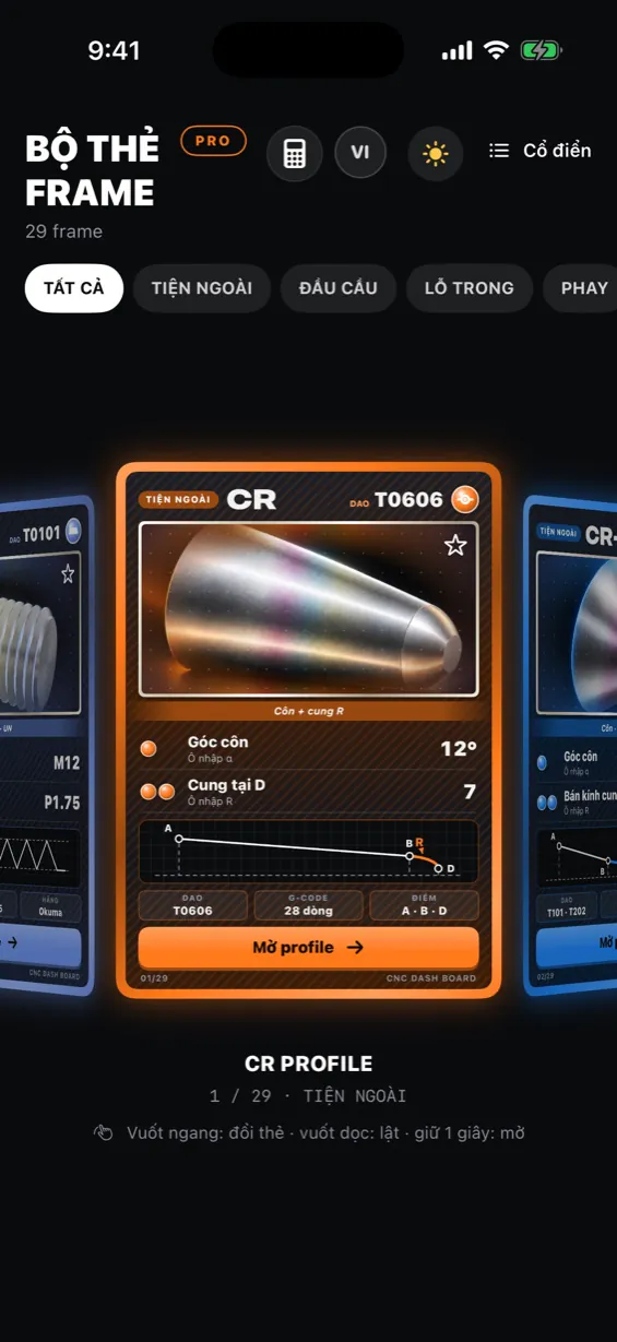
Pick a profile
The first screen asks “Bạn cần gia công gì?” (what do you need to machine?). Pick a type: TIỆN NGOÀI (outer turning), ĐẦU CẦU (ball end), LỖ TRONG (bore), PHAY (milling) or REN (thread).
- For outer turning, then pick what you see on the drawing — CÔN (taper), ĐOẠN TRỤ (cylinder), ĐUÔI (tail), KHUNG BẬC (step) and the number of arcs — and the list below keeps only the matching profiles.
- Already know the name? Switch to Tìm theo tên (search by name).
PRO adds the card ring: swipe sideways to change card, swipe up/down to flip it over, hold for 1 second to open.
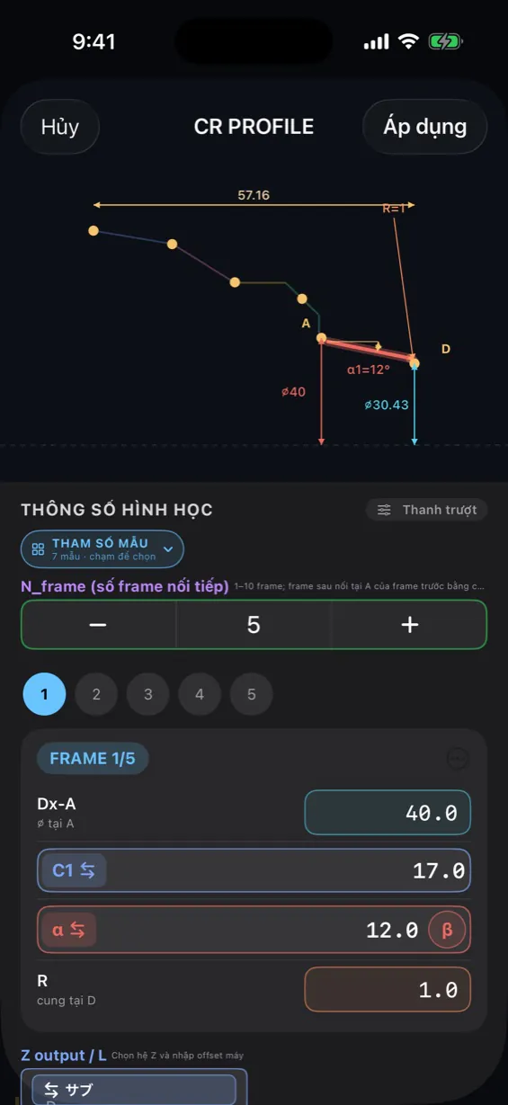
Enter the drawing numbers
Opening a profile brings up the Thông số (parameters) sheet. The preview at the top redraws as you type, with ⌀, lengths, angles and point names just like the drawing.
- THAM SỐ MẪU (sample sets): tap to load a ready-made set of numbers, then adjust it to your part.
- N_frame − / +: chain several sections (tapers, cylinders, shoulders) on one part; the 1, 2, 3… buttons open each frame. For CR and NKE RCR, multiple frames are a PRO feature (the free edition uses 1 frame).
- Labels with a ⇆ (e.g. C1 ⇆, α ⇆): tap the label to switch that field to the other quantity your drawing gives.
- Thanh trượt (sliders): drag to adjust quickly within the valid range. When done, tap Áp dụng (apply).
If a value can't build the shape, the app tells you right away instead of producing wrong G‑code.
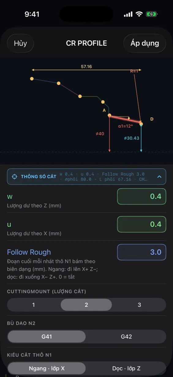
Cutting parameters
Open the THÔNG SỐ CẮT (cutting parameters) section of the sheet:
- w / u — stock left in Z and in X for the finishing tool.
- CuttingMount — depth of cut per roughing layer.
- Follow Rough — the end of each roughing pass follows the profile for this length (mm); 0 = off.
- Bù dao N2 — tool compensation G41 or G42. Kiểu cắt thô N1 — roughing style: Ngang (layers in X) or Dọc (layers in Z).
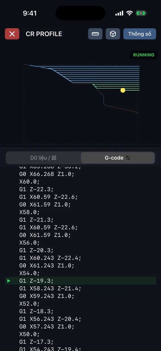
Tool path simulation
Close the parameters sheet and tap the drawing to run the simulation: each roughing layer, then the finishing tool along the profile.
- The G‑code sits right below; the line being run has a ▶ and a highlight, so you can match every block to the tool movement.
- Tapping again while it runs jumps to the end result. Hold the drawing for about half a second to reopen the parameters.
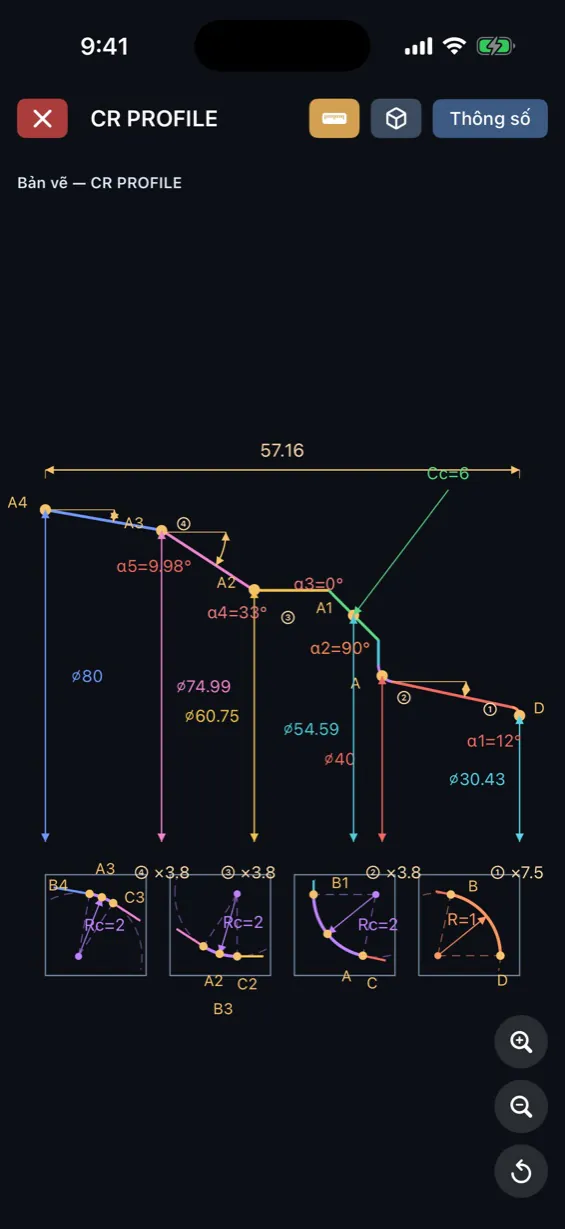
図 drawing
The ruler button in the top bar opens the drawing: diameters, lengths, angle α and radius R of every frame.
- Small arcs are magnified in detail cells below (×2.9, ×3.8…) so the tangent points are easy to read.
- Use + / − / ⟲ or two fingers to zoom in and out.
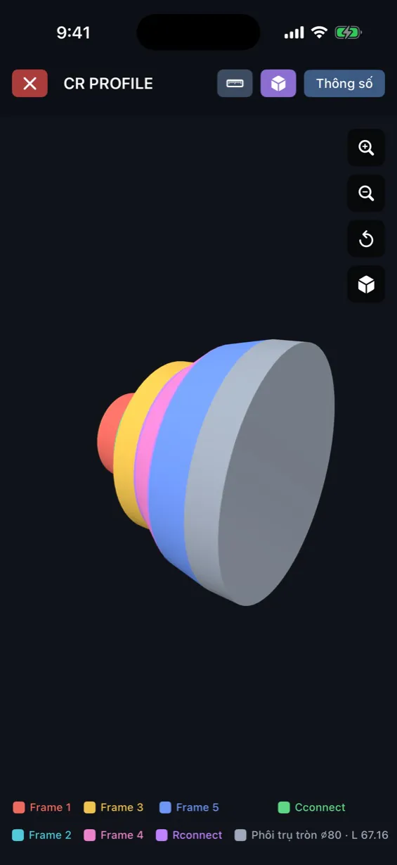
3D model
The cube button opens the 3D model of the part. Each frame has its own colour, with a legend below.
- Rotate with one finger, zoom with two fingers or + / −, and ⟲ to go back to the starting view.
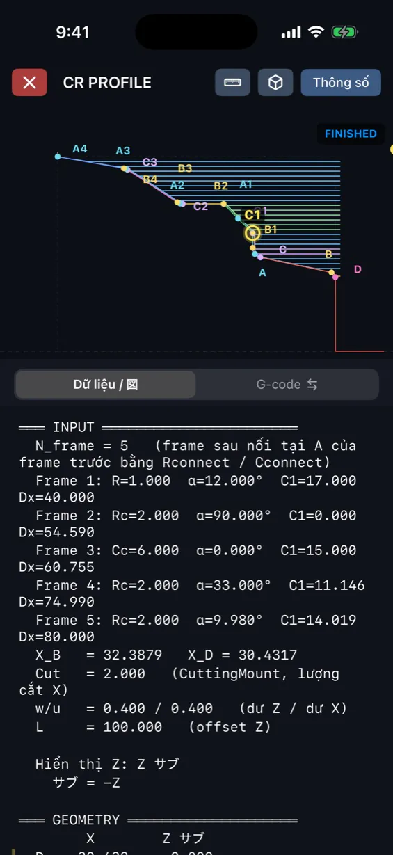
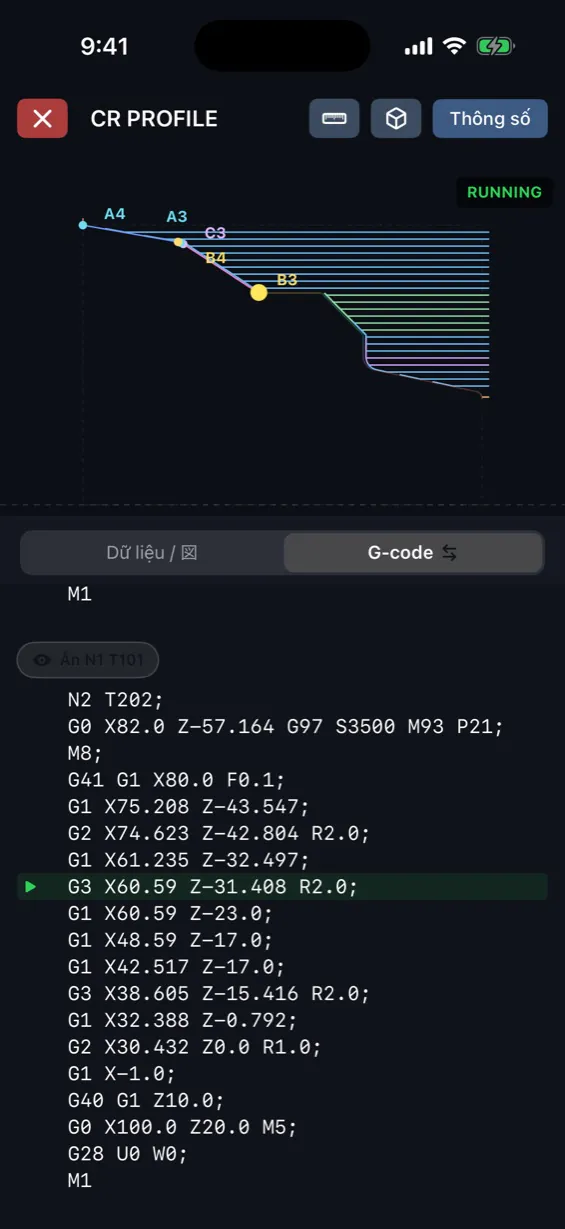
Data and G‑code
Below the drawing there are two pages: Dữ liệu / 図 (data / drawing) and G‑code.
- The Dữ liệu page lists the inputs, the coordinates of every point and the roughing layers. Tap a point line (e.g. C1) and that point lights up in yellow on the drawing.
- The G‑code page: the free edition has the G‑code program (the app's own N1 roughing / N2 finishing). For CR, CR-H, RCR, KANTSUGI, TAIL R+r, WASHER, NKE RCR and 3R, PRO lets you tap the tab again (marked ⇆) to switch to FANUC G‑code (G71 / G70 cycles) or OKUMA G‑code (G85 / G87 cycles with NLP).
Milling on the lathe · PRO
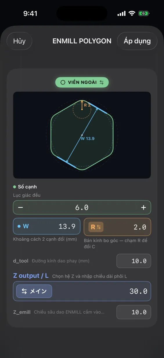
Milling profiles use a live tool and the C axis. Example ENMILL POLYGON: choose VIỀN NGOÀI ⇆ (outer profile) or inner pocket, number of sides, width across flats W, corner radius R and tool diameter.
- Z output / L sets the Z origin (メイン / サブ) and the stock length.
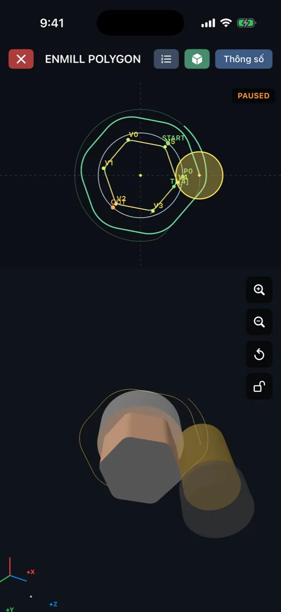
- In 3D the stock turns with the C axis and the end mill removes material exactly as the program says — leftover stock or gouges show up at once.
Milling needs the PRO unlock (one-time purchase).
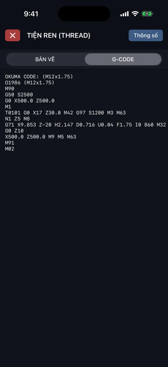
Threading
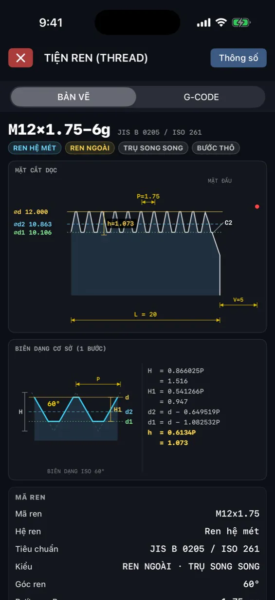
Type the thread code (e.g. M12x1.75) — the app recognises the thread system (M, R, G, UN) and shows ✓ Mã hợp lệ (valid code); Các loại ren hỗ trợ (supported threads) lists the codes — tap one to fill it in. Pipe threads R / Rc / PT, Rp / Ps, G / PF are part of PRO.
- Enter the thread length L, the entry point V and the Z origin.
- Choose the control Okuma / Fanuc, external / internal thread, and the G71/G76 or G33/G92 cycle.
- The BẢN VẼ (drawing) page describes the thread: a section with ⌀d / ⌀d2 / ⌀d1, pitch P, height h, L and V; the 60° (or 55°) basic profile with its formulas; and info cards giving the standard and the 6g / 6H tolerance for metric threads.
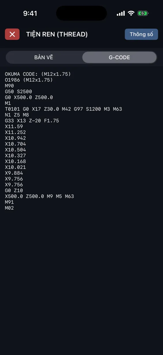
- The G-CODE page: G33/G92 prints every pass as its own X line; G71/G76 packs the whole thread cycle into one block.
Machining calculator
The formulas you reach for next to the machine — cutting speed, spindle speed, feed, roughness, time, power, tap drills, fits, materials — right in the app, no pocket calculator or handbook needed.

Open the calculator
On the profile picker, tap the round calculator button next to VI / EN and ☀︎/☾ (in both the list and the card ring).
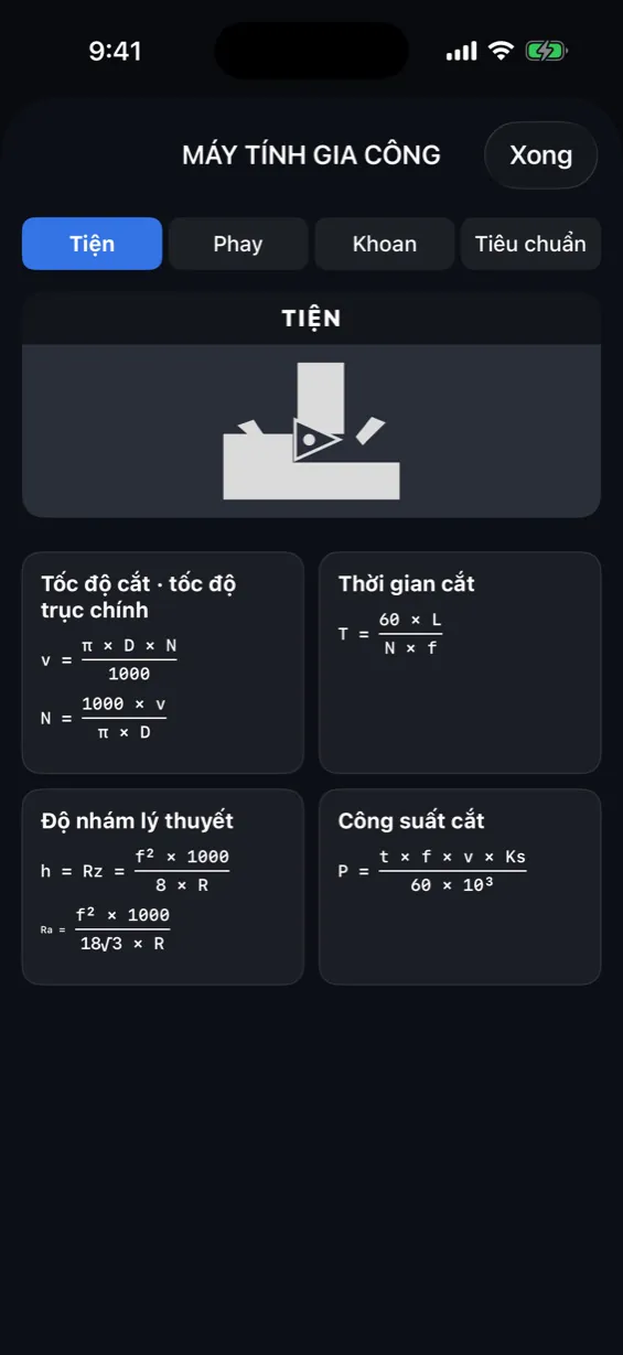
Pick a group
Four groups: Turning · Milling · Drill · Standard, each a set of formula cards. Tap the open group again to return to the welcome screen.
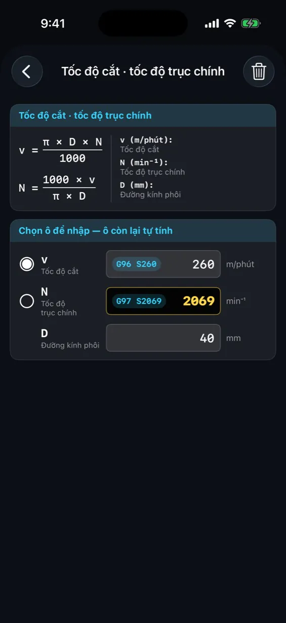
Type — the result shows at once
Tap a card: the top panel shows the formula and what each symbol means, the bottom panel the input fields. Results update as you type (black box, yellow number) — there is no Calculate button. Tap the G96 S… / G97 S… tag to copy the command.
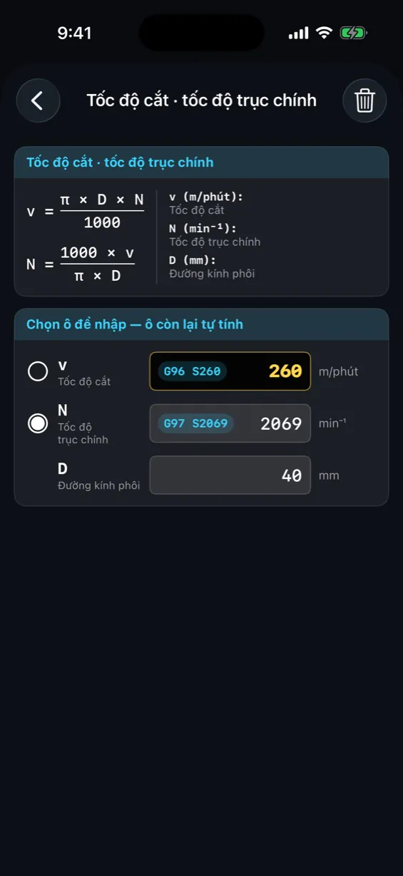
Pick the field you type
Two-way formulas (v ⇄ N, fz ⇄ F, mm ⇄ inch): the radio button marks the field you type, the other one is solved. Tap a radio button or the result box to swap — the current number is kept.
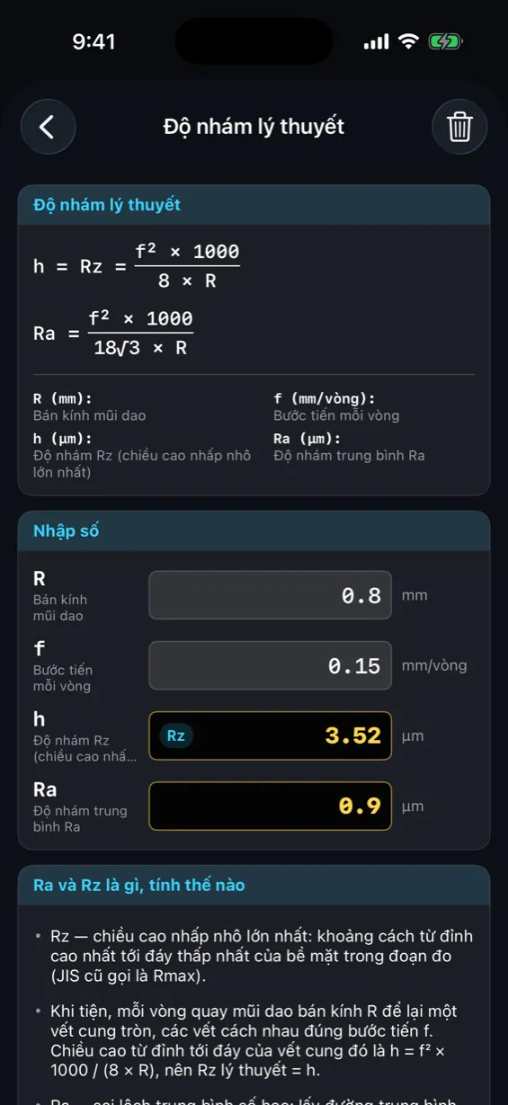
Surface roughness
Enter the nose radius R and feed f to get the theoretical Rz and Ra. Example: R0.8, f 0.15 → Rz 3.52 µm, Ra 0.9 µm. An explanation of Ra and Rz sits below.
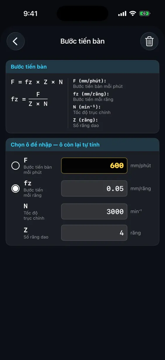
Milling: table feed
F = fz × Z × N, plus cutting power and time. Example: fz 0.05, 4-flute cutter, 3000 min⁻¹ → F600 mm/min. The Drill group has speed, time, and power · thrust · torque.
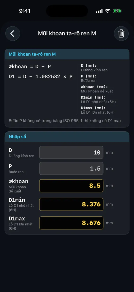
Tap drill · taper
In Standard: type the M thread diameter and pitch → suggested drill and minimum / maximum minor bore D1 for 6H. Example: M10×1.5 → ⌀8.5. Also taper angle ⇄ 1 : x and mm ⇄ inch.
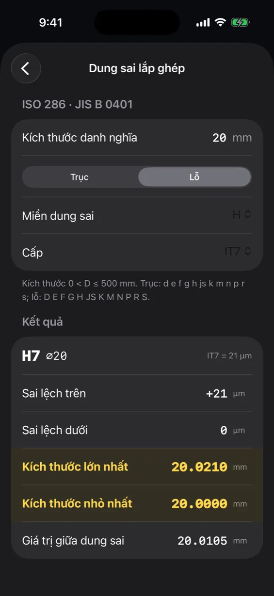
Fit tolerances
ISO 286 / JIS B 0401: enter the size, choose Shaft or Bore, the tolerance zone and IT grade → upper / lower deviation and maximum / minimum size. Example: ⌀20 H7: +21 µm / 0.
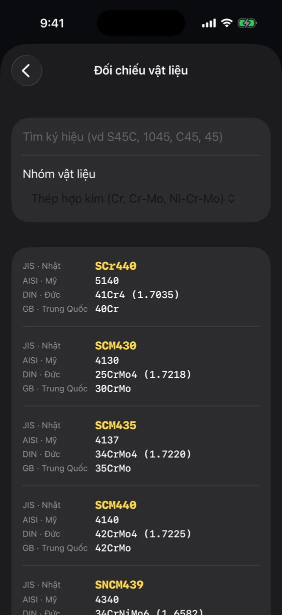
Material cross-reference
Search steel grades across JIS · AISI · DIN · GB (e.g. S45C, 1045, C45). Next to it is Unit conversion: length, speed, mass, force, pressure, power, torque.
The Ks and K factors and the equivalent steel grades are reference values — check them against your tool catalogue and material certificate. The trash button clears every number; tapping back into a field that holds a number selects it, so typing overwrites it.
Taking the program to the machine
Before running on the real machine:
- Check that tool numbers, M-codes and the Z origin match your machine and setup.
- Dry-run without cutting, with reduced rapid speed the first time.
- Compare the G‑code with the simulation — every line was highlighted as the simulation ran through it.
Always verify the program, confirm M-codes for your machine, and dry-run before cutting.