CNC Dash Board
Biểu tượng ứng dụng CNC Dash Board

G‑code logic for CNC lathes

Type the drawing dimensions, get an instant machining simulation and smooth G‑code output.

Pick a profile, enter the numbers from your drawing, watch the tool simulation, and take the program to the machine.

Supported machines

What it does for you

Less hand math, fewer mistakes, faster to the machine

Right on your iPhone — no computer, no CAD.

20 minutes → 20 seconds

No more working out Xb and Zb with tan and sin, then crossing it out. Type the drawing numbers — the app finds every tangent point, arc centre and tool path.

See the tool path before you cut

Roughing and finishing simulated pass by pass, a dimensioned 図 drawing and a 3D model. Mistakes show up on screen, not on the part.

G‑code for your control

G‑code for FANUC machines in the free edition; PRO adds FANUC G71 / G70 and OKUMA cycle programs. Pick the サブ / メイン Z zero, tool compensation and roughing style — no hand-editing line by line.

Start from real samples

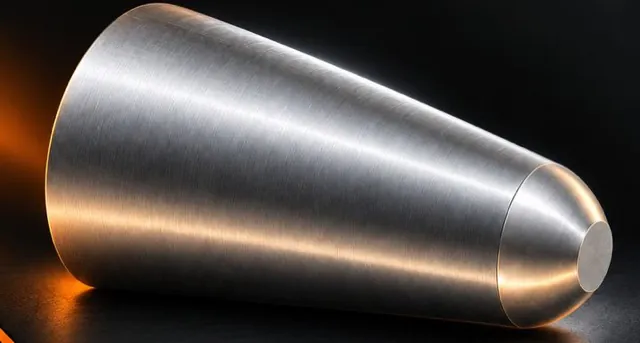
Sample sets taken from real drawings: taper pins, Morse MT2 shank, 60° centre point, check valve… One tap fills every field.
Profile library

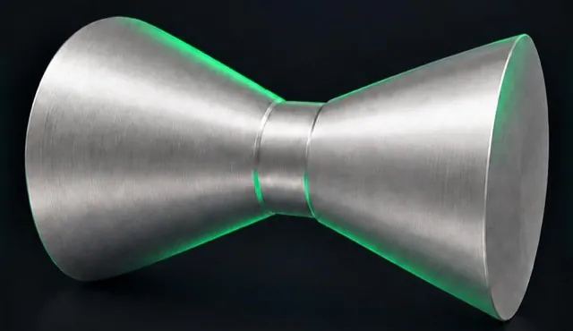
29 profiles — just fill in the numbers

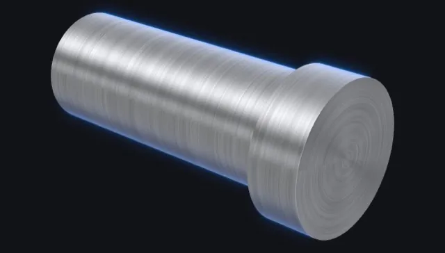
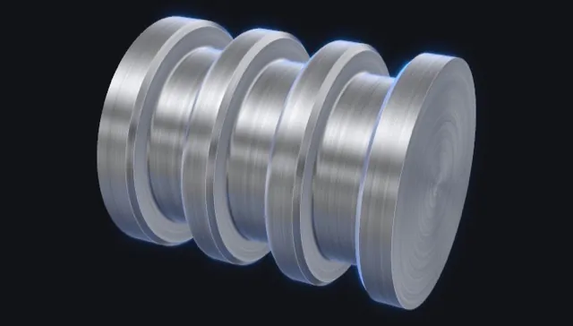
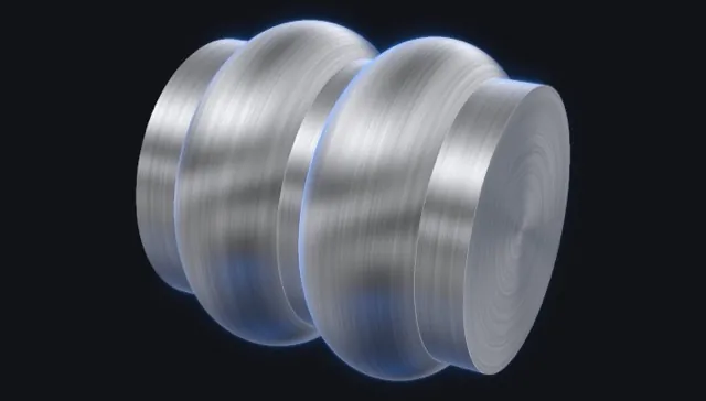
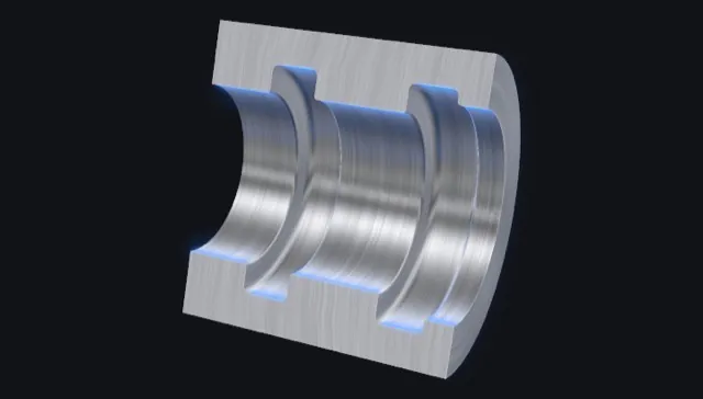
Outer turning, bores, ball ends, C-axis milling and threading. Pick the shape that matches your part.

How it works

From drawing to G‑code in 4 steps

  1. 1

    Pick a profile

    Filter by what you see on the drawing — cone, cylinder, number of arcs, tail or step — or search by name.

  2. 2

    Type the drawing numbers

    Diameter, length, angle α, radius R. The preview redraws as you type.

  3. 3

    Simulate and check

    Run the tool simulation, check the 図 drawing and 3D; the G‑code line being run is highlighted.

  4. 4

    Take it to the machine

    Choose the control and Z origin, take the G‑code to the machine, and dry-run before cutting.
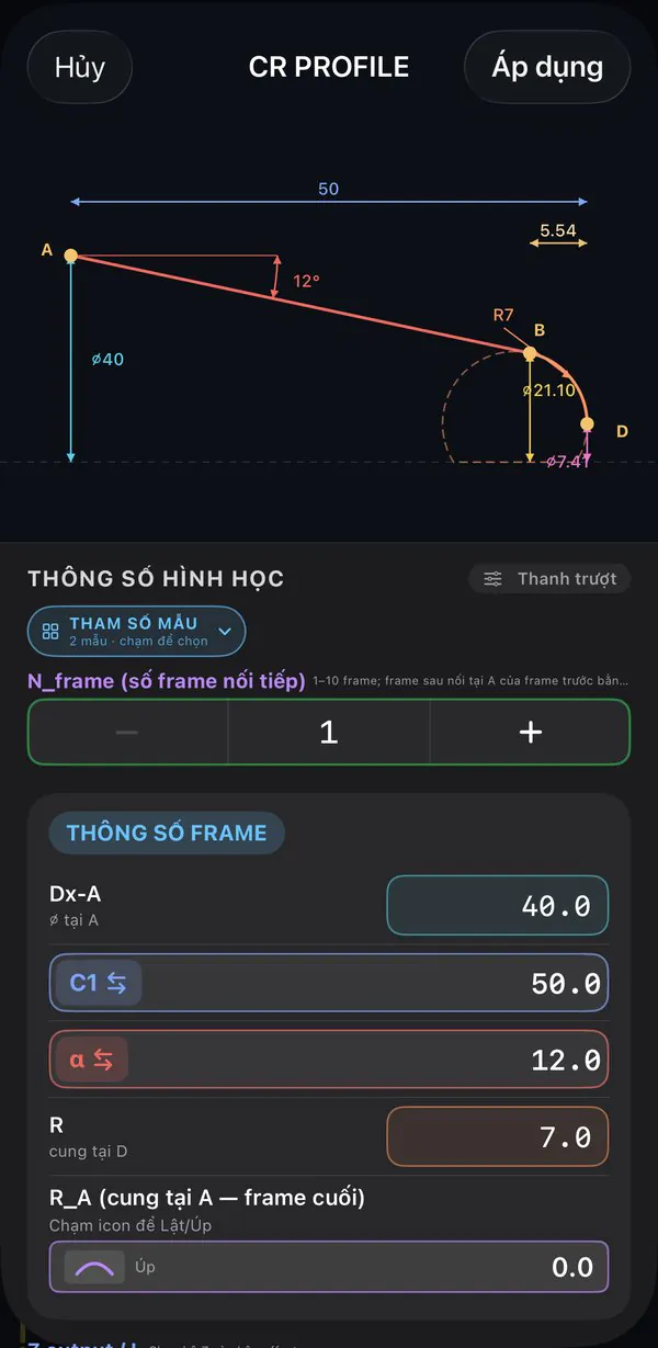
Enter numbers the way you read a drawing
STEP 2

Enter numbers the way you read a drawing

The preview shows diameters, lengths, the angle and points A, B, D like a real drawing. Start from a sample set or type Dx, length, angle α and radius R.

STEP 3

G‑code that follows the cut

The program sits under the simulation, and the line being run is highlighted, so you can match every block to the tool path before it reaches the machine.
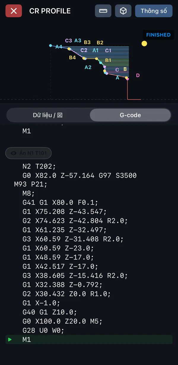
G-code that follows the cut

Always verify the program, confirm M-codes for your machine, and dry-run before cutting.

Drawing in hand, G‑code in seconds

Pick the profile that matches your part and let the app do the math.

Supported machines

FANUC

Lathes with a FANUC control (Series 0i-T and similar). Photo: Citizen Miyano BNJ-42 with a bar feeder — FANUC 0i-TF, two spindles, two turrets.

Setting the work origin

Every coordinate in the app's program is measured from one work origin: X0 = spindle centreline, Z0 = the part face after facing (サブ mode). The program has no coordinate-setting block (G50 X… Z…) — the machine must know that origin for each tool, usually through the tool geometry offsets:

X0 = spindle centreline, X is a diameter. Z0 サブ = part face. Z0 メイン = moved L mm towards the chuck. Z+ points away from the chuck.
  1. Clamp the stock, call the tool in MDI (e.g. T0101) and take a light facing cut. Keep Z, back off in X.
  2. OFS/SET → OFFSET → GEOMETRY, move the cursor to the tool's offset number (G001 for T0101), type Z0 → MEASURE. The control works out the distance from the tool tip to Z0.
  3. Turn a short diameter, keep X, back off in Z. Measure it with a micrometer (e.g. 41.52) → type X41.52 → MEASURE.
  4. On the same page enter the nose radius R (e.g. 0.8 / 0.4) and the tip direction T — needed for G41 / G42 compensation when finishing.
  5. Repeat for the finishing tool T0202 and the others — touch the faced end / turned diameter, no need to cut again.
  6. Whole batch off in Z (new stock, new clamping): correct it once in WORK SHIFT instead of editing every tool.

Two-path machines (two spindles / two turrets like the BNJ-42): each path has its own offset table — set the origin on the path that will run the program. Key names can differ between control generations; check your machine manual.

Z output サブ / メイン in the app

Every turning profile has a Z output / L field — pick the Z system that matches how you set the origin on the machine:

  • サブ (default): Z0 at the part face, Z negative towards the chuck.
  • メイン: Z0 moved L mm towards the chuck (type L), L is added to every Z. Use it when the machine's Z origin sits on another reference face (e.g. the clamping face) L mm from the part face.

Example, default CR, point A at ⌀40, 50 mm from the face: サブ X40.0 Z-50.0 · メイン (L = 100) X40.0 Z50.0; the face Z0.0 → Z100.0. Changing Z output only changes the Z numbers in the G‑code; the simulation does not restart.

What the app outputs

  • One block per tool: N1 T101 roughing, N2 T202 finishing — T101 = tool 1 + offset 01.
  • G99 feed in mm/rev, G96 S… constant surface speed (m/min), G97 S… fixed rpm.
  • Roughing layer by layer with G0 / G1 (no G71 cycle) — every line is visible in the simulation.
  • Finishing with nose compensation G41 / G42, cancelled by G40; arcs G2 / G3 … R.
  • Each block ends with G28 U0 W0 to the machine reference point.

Excerpt of a real program

N1 T101;
G99 G0 X48.19 Z10.0 G96 S220 M93 P21;
Z1.0 M8;
G1 Z-57.7 F0.3;
…
G28 U0 W0;
N2 T202;
G41 G1 X50.19 F0.1;
G3 X39.858 Z-49.742 R2.0;
…
G40 G1 Z10.0;

Before you run

  • Tool / offset numbers in the program (T101, T202) match the tools on the turret.
  • M-codes (coolant, spindle, maker-specific codes like M93 P21) are right for your machine.
  • Run Single Block with reduced rapid: the first move to Z1.0 must stop just in front of the face — if not, the Z origin is wrong.

Supported machines

OKUMA

OKUMA lathes with the OSP control (e.g. OSP-P300LA). Programs follow a sample that runs on a real OSP machine of an app user. OKUMA programs are part of PRO.

Setting the work origin

Same work origin as FANUC: X0 = spindle centreline, Z0 = part face (サブ mode). On OSP the Z origin is stored as the work zero (Zero set), and each tool's length lives in Tool offset:

X0 = spindle centreline, X is a diameter. Z0 サブ = part face. Z0 メイン = moved L mm towards the chuck. Z+ points away from the chuck.
  1. Face the part with the reference tool and keep Z.
  2. Open the ZERO SET screen, pick the Z axis, enter 0 → CAL: the current position becomes the work Z0 (stored in the system variable VSZOZ).
  3. TOOL OFFSET screen: for each tool, touch the known face / diameter, enter the measured value → CAL. The X / Z offset goes into the offset number = the first two digits of the T code (T010101).
  4. Enter the nose radius in the nose-R number = the last two digits (T010101): 0.8 for the ARAI 0.8 roughing tool, 0.4 for the SIAGE 0.4 finishing tool.
  5. Dry run: the N1 Z1.0 line must stop just in front of the face.

The app does not print a VSZOZ= line in the program: hard-coding the Z origin of one setup into every program is wrong for the next setup — the origin is always set on the machine. Screen / key names can differ between OSP generations; check your machine manual.

Z output サブ / メイン in the app

Every turning profile has a Z output / L field — pick the Z system that matches how you set the origin on the machine:

  • サブ (default): Z0 at the part face, Z negative towards the chuck.
  • メイン: Z0 moved L mm towards the chuck (type L), L is added to every Z. Use it when the machine's Z origin sits on another reference face (e.g. the clamping face) L mm from the part face.

Example, default CR, point A at ⌀40, 50 mm from the face: サブ X40.0 Z-50.0 · メイン (L = 100) X40.0 Z50.0; the face Z0.0 → Z100.0. Changing Z output only changes the Z numbers in the G‑code; the simulation does not restart.

What the app outputs

  • Six-digit tool code T010101 = tool offset no. · tool no. · nose-R offset no.
  • LAP cycles: G85 roughs along the profile defined in the NLP… block (G81 longitudinal / G82 facing … G80); the control splits the layers from D (depth) and U / W (stock). G87 runs the same profile again to finish.
  • Arc radius written with L (e.g. G3 X… Z… L7.0), nose compensation G41 / G42.
  • The NKE RCR bore program starts O2000 / M90 / G50 S2500 — on OKUMA G50 S is the spindle speed limit, not a coordinate setting.
  • Park position Z500.0, always retracting on the face side.
  • OKUMA output: CR, CR-H, RCR, KANTSUGI, TAIL R+r, WASHER, NKE RCR, 3R, JAW ENMILL, THREADING — on the G‑code page tap the tab again (⇆) to switch FANUC ⇄ OKUMA.

Excerpt of a real program

T010101(ARAI 0.8)G0 X41.0 Z30.0 M42 G97 S1600 M3 M63
G96 S220
N1 Z1.0 M8
G85 NLP2 D2.0 U0.4 W0.4 F0.3
NLP2 G81
G0 X7.407 Z2.0
G42 G1 Z0.0 F0.15 I-1
G3 X21.101 Z-5.545 L7.0
G1 X40.0 Z-50.0
G40 G0 X45.0 I1
G80
…
T030303(SIAGE 0.4)G0 X41.0 Z30.0 M42 G97 S2000 M3 M63
G87 NLP2

Before you run

  • The tool numbers in the sample (T010101 roughing, T030303 finishing) are fixed — change them to your turret before running.
  • Check the M-codes (M42 gear range, M63, M8 / M9…) for your machine.
  • Run Single Block the first time and check the G85 layers the control generates leave the right stock.